
Learn what a high-frequency PCB is and why it is essential for 5G communication, automotive radar, satellite systems, and RF electronics. Discover key high-frequency PCB materials, dielectric constant (Dk), dielectric loss (Df), impedance control, and PCB design considerations.
What Is a High-Frequency PCB?
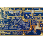
A high-frequency PCB is a specialized printed circuit board designed to transmit high-speed and high-frequency signals with minimal signal loss. In most cases, a PCB operating above 1 GHz is classified as a high-frequency PCB. These circuit boards are widely used in RF, microwave, millimeter-wave, and high-speed digital applications where signal integrity and electrical stability are critical.
As technologies such as 5G communication, automotive electronics, IoT devices, satellite communication, and cloud computing continue to evolve, the demand for high-frequency PCB manufacturing is growing rapidly worldwide. Compared with traditional FR-4 boards, high-frequency PCB materials offer lower dielectric loss, more stable impedance, lower moisture absorption, and better thermal reliability.
Today, high-frequency PCBs are essential components in:
- 5G base stations
- Automotive radar systems
- Satellite communication equipment
- Wi-Fi 6 and Wi-Fi 7 devices
- Aerospace electronics
- High-speed servers and data centers
- RF and microwave modules

Why High-Frequency PCBs Matter
Modern electronic systems are transmitting more data at much higher frequencies than ever before. Standard PCB materials often struggle to maintain signal quality under these conditions. At high frequencies, even small inconsistencies in PCB materials can cause:
- Signal attenuation
- Electromagnetic interference (EMI)
- Increased insertion loss
- Impedance instability
- Data transmission errors
High-frequency PCB technology solves these issues by using advanced laminate materials and optimized RF PCB design techniques.
The primary goal of a high-frequency PCB is to maintain signal integrity while minimizing signal loss during transmission.
Key Parameters of High-Frequency PCB Materials
Low Dielectric Constant (Dk)
The dielectric constant, commonly referred to as Dk, measures how much electrical energy a PCB material can store. Lower Dk values allow signals to travel faster through the substrate.
Signal transmission speed is inversely proportional to the square root of the dielectric constant:
v∝1Dkv \propto \frac{1}{\sqrt{D_k}}
This means:
- Lower Dk = Faster signal transmission
- Higher Dk = Greater signal delay
Stable dielectric performance is extremely important in high-frequency RF and microwave circuits because fluctuations can directly impact impedance control and timing accuracy.
Typical Dk values include:
| Material | Typical Dk |
|---|---|
| PTFE | 2.2 |
| Rogers RO4003C | 3.38 |
| Standard FR-4 | 4.2–4.8 |
| Ceramic-filled laminates | 6–10+ |

Low Dielectric Loss (Df)
The dielectric loss factor (Df) measures how much signal energy is lost as heat during transmission. Lower Df values improve RF signal quality and reduce attenuation.
Common Df values include:
| Material | Typical Df |
|---|---|
| Rogers RT5880 | 0.0009 |
| PTFE materials | 0.0008–0.002 |
| Standard FR-4 | 0.015–0.025 |
For high-speed applications such as:
- 77 GHz automotive radar
- 5G millimeter-wave antennas
- High-speed networking
- Aerospace RF systems
ultra-low-loss PCB materials are essential.
More information about RF laminate technology can be found at Rogers Corporation.
Impedance Control in High-Frequency PCB Design
Controlled impedance is one of the most important requirements in high-frequency PCB manufacturing. Poor impedance matching can cause signal reflections, transmission loss, and unstable RF performance.
Typical impedance structures include:
- 50-ohm single-ended traces
- 90-ohm differential pairs
- 100-ohm differential impedance
To achieve accurate impedance control, PCB engineers must carefully optimize:
- Trace width
- Copper thickness
- Dielectric thickness
- PCB stackup
- Ground reference planes
Design software such as ADS, HFSS, and HyperLynx is commonly used to simulate and verify impedance performance before production.

Moisture Absorption and Thermal Stability
Moisture absorption can significantly affect the electrical properties of high-frequency PCB materials. When moisture enters the substrate, both Dk and Df can change, resulting in unstable RF performance.
Advanced materials such as PTFE and LCP provide extremely low moisture absorption rates, making them suitable for harsh outdoor and aerospace environments.
Thermal reliability is equally important. High-frequency PCB materials must maintain dimensional stability during thermal cycling and soldering processes.
Critical thermal properties include:
- Low coefficient of thermal expansion (CTE)
- High glass transition temperature (Tg)
- Strong copper adhesion
- Excellent heat resistance
Common High-Frequency PCB Materials
PTFE-Based PCB Materials
PTFE is widely regarded as one of the best materials for microwave and millimeter-wave applications due to its ultra-low loss characteristics.
Popular PTFE laminates include:
- Rogers RT5880
- Rogers RT5870
- Taconic RF materials
Applications include:
- Satellite communication
- Aerospace systems
- Automotive radar
- RF test equipment
Learn more about advanced PCB laminate materials at Taconic Advanced Dielectric Materials.
Hydrocarbon Resin Materials
Hydrocarbon ceramic laminates combine excellent RF performance with easier manufacturing compared to pure PTFE materials.
Common products include:
- Rogers RO4350B
- Rogers RO4003C
These materials are widely used in:
- 5G antennas
- RF amplifiers
- Power dividers
- Wireless communication modules
Modified Epoxy Resin Materials
Modified epoxy laminates provide a cost-effective solution for mid-frequency applications while remaining compatible with standard FR-4 processing techniques.
Typical applications include:
- Wi-Fi modules
- Bluetooth devices
- Consumer electronics
- IoT hardware
LCP (Liquid Crystal Polymer)
LCP materials offer:
- Ultra-low moisture absorption
- High flexibility
- Excellent millimeter-wave performance
They are increasingly used in wearable electronics and flexible RF circuits.
Additional technical resources about high-speed PCB materials are available from Panasonic Industry Electronic Materials.

Applications of High-Frequency PCBs
5G Communication Systems
High-frequency PCBs are critical for supporting the high-speed signal transmission required in 5G infrastructure and millimeter-wave communication systems.
Automotive Radar
Modern radar systems operating at 24 GHz and 77 GHz rely heavily on low-loss PCB materials to maintain accurate target detection and signal stability.
Satellite Communication
Satellite systems require ultra-reliable RF transmission over long distances, making PTFE-based PCB materials a preferred solution.
High-Speed Data Centers
As networking speeds continue to increase beyond 400G and 800G, high-frequency PCB technology becomes increasingly important for servers and optical communication systems.
Consumer Electronics
Smartphones, wireless charging systems, wearable devices, and Wi-Fi 7 products all benefit from advanced RF PCB technology.
Conclusion
High-frequency PCB technology has become an essential part of modern electronics. From 5G communication and automotive radar to satellite systems and high-speed networking, advanced RF PCB materials help ensure reliable signal transmission and stable electrical performance.
Compared with standard FR-4 boards, high-frequency PCB materials provide:
- Lower dielectric constant
- Lower dielectric loss
- Better impedance stability
- Lower moisture absorption
- Improved thermal reliability
As electronic systems continue moving toward higher frequencies and faster data rates, the importance of high-frequency PCB design and manufacturing will only continue to grow.