
RT5870 & RT5880 High-Frequency PCB Materials: Properties, Sizes, and Applications
High-frequency circuit design relies heavily on stable dielectric performance, especially in RF, microwave, and millimeter-wave systems. Materials such as RT5870 and RT5880 are widely used in antenna systems, radar modules, satellite communications, and 5G infrastructure due to their low dielectric loss and excellent electrical stability.
Key Electrical Properties
RT5870 and RT5880 are both advanced PTFE-based laminates designed for high-frequency applications, offering low dielectric constant (Dk) and ultra-low dissipation factor (Df).
- RT5870
- Dielectric Constant (Dk): 2.33 ± 0.02 @ 10 GHz
- Dissipation Factor (Df): ≤ 0.0012 @ 10 GHz
- RT5880
- Dielectric Constant (Dk): 2.20 ± 0.02 @ 10 GHz
- Dissipation Factor (Df): ≤ 0.0009 @ 10 GHz
RT5880 provides slightly lower dielectric constant and loss, making it more suitable for ultra-high-frequency and low-loss transmission designs.
Material Comparison Overview
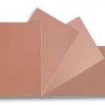


Both materials belong to the same class of high-frequency laminates but differ in performance optimization:
- RT5870: Balanced performance for general RF and microwave circuits
- RT5880: Optimized for extremely low loss and higher-frequency stability
Typical applications include:
- Patch antennas
- Radar modules
- Satellite communication systems
- 5G base station RF boards
- Microwave filters and couplers
Standard Sizes and Fabrication Options
These laminates are available in industry-standard sheet formats to support scalable PCB manufacturing:
- Standard panel sizes
- 12 × 18 inches
- 18 × 24 inches
- Standard thickness options
- 0.127 mm
- 0.254 mm
- 0.381 mm
- 0.508 mm
- 0.787 mm
- 1.575 mm
- 3.175 mm
- Copper cladding options
- 0.5 oz
- 1 oz
These flexible configurations make them suitable for both compact RF modules and large antenna array systems.
Electrical Performance Advantages


The main advantages of RT5870 and RT5880 include:
- Extremely low signal loss at microwave frequencies
- Stable dielectric performance over frequency changes
- Excellent dimensional stability
- Suitable for multilayer RF and hybrid PCB structures
- Reliable performance in harsh environmental conditions
These properties make them a preferred choice in aerospace, defense, and high-speed wireless systems.
Industry Context and Manufacturer
These materials are developed by Rogers Corporation, a global leader in high-performance engineered materials for RF and microwave applications.
Their RO4000 and RO3000 series laminates are widely adopted in next-generation wireless communication systems.
Design Considerations
When selecting between RT5870 and RT5880, engineers typically evaluate:
- Operating frequency range
- Insertion loss requirements
- Impedance stability
- Thermal and mechanical constraints
- Manufacturing cost vs. performance balance
RT5880 is often preferred for ultra-low-loss antenna designs, while RT5870 is used where cost-performance balance is important.