
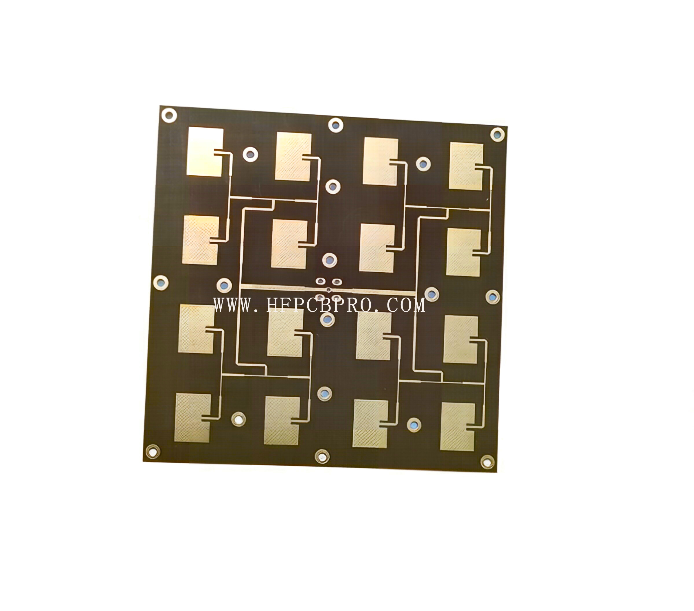
High-frequency printed circuit boards (PCBs) are specialized PCBs designed specifically for transmitting and processing high-frequency signals (typically frequencies above 1 GHz). They are widely used in high-frequency and high-speed signal processing applications such as 5G communications, radar systems, satellite communications, high-speed digital equipment, and automotive electronics. The following is a detailed introduction to high-frequency PCBs:
I. Key Features
Low-Loss Materials: High-frequency PCBs utilize specialized substrates with low dielectric constant (Dk) and low dielectric loss (Df), such as polytetrafluoroethylene (PTFE) and ceramic-filled materials, to minimize signal loss and distortion during transmission.
Precision Manufacturing Processes: High-frequency circuit boards require high-precision manufacturing processes, such as laser direct imaging (LDI) and high-precision etching, to ensure the accuracy and consistency of fine circuit patterns.
Strict Impedance Control: High-frequency circuit boards require precise control of the characteristic impedance of transmission lines (typically 50Ω or 75Ω) to achieve signal matching and minimize reflections, ensuring the stability and reliability of signal transmission.
II. Design Considerations
Transmission Line Design: High-frequency signals must be treated as propagating electromagnetic waves and require transmission lines (such as microstrip lines or striplines) for signal transmission. During design, line width and spacing must be calculated based on signal frequency and board characteristics to ensure continuous characteristic impedance.
Routing Principles:
Critical signal lines (such as clock and RF lines) should be routed as short as possible, avoiding right-angle turns and using 45° angles or curved paths instead.
Differential pairs must be routed with strict equal length, equal spacing, and parallel alignment to maintain coupling and impedance balance.
Follow rules such as 3W/5H to control crosstalk; that is, the spacing between signal lines should be no less than three times the line width, and the spacing between signal lines and ground planes should be no less than five times the line height.
Via Optimization: Vias are major sources of impedance discontinuities and signal loss; their use should be minimized in high-frequency designs. When their use is unavoidable, they must be optimized, such as by using small-diameter vias or employing back-drilling techniques to remove conductive stubs from unconnected layers.
Power and Ground Plane Design: Use a multilayer board structure with dedicated, continuous power and ground planes, and tightly couple them to form a planar capacitor, thereby enhancing decoupling. Place decoupling capacitor networks in layers near the IC power pins to ensure that power impedance remains low within the target frequency range.
III. Manufacturing Process
Material Treatment: For difficult-to-bond materials such as PTFE, plasma treatment must be applied to the hole walls after drilling to activate the surface and enhance the adhesion of the hole metallization (copper plating).
Fine-Line Fabrication: Low-profile copper foil is used to minimize conductor loss, and high-precision dry film or liquid photoresist is employed for pattern transfer to ensure steep sidewalls and consistent line widths.
Surface Treatment: For high-frequency PCBs, electrochemical nickel-gold (ENIG) or silver plating is preferred for surface treatment to reduce high-frequency losses.
IV. Application Areas
Communications: High-frequency PCBs are widely used in communication and networking equipment such as 5G base stations, fiber optic communication devices, routers, and switches, supporting high-speed data transmission and complex signal processing.
Radar and Satellite Systems: High-frequency PCBs are used for signal processing in radar systems and high-frequency signal transmission in satellite communications, ensuring signal transmission stability and reliability.
Automotive Electronics: In the automotive electronics sector, high-frequency circuit boards are used in the design of in-vehicle communication systems, infotainment systems, and driver assistance systems, meeting the demands of high-speed data transmission and complex signal processing.
Medical Devices: High-frequency circuit boards are also used in medical diagnostic equipment, image processing systems, and monitoring devices, supporting high-speed data transmission and signal processing to enhance the performance and accuracy of medical equipment.
Translated with DeepL.com (free version)