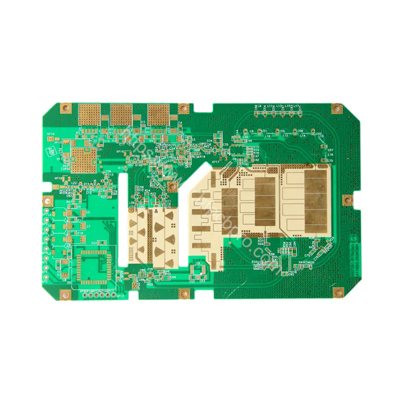
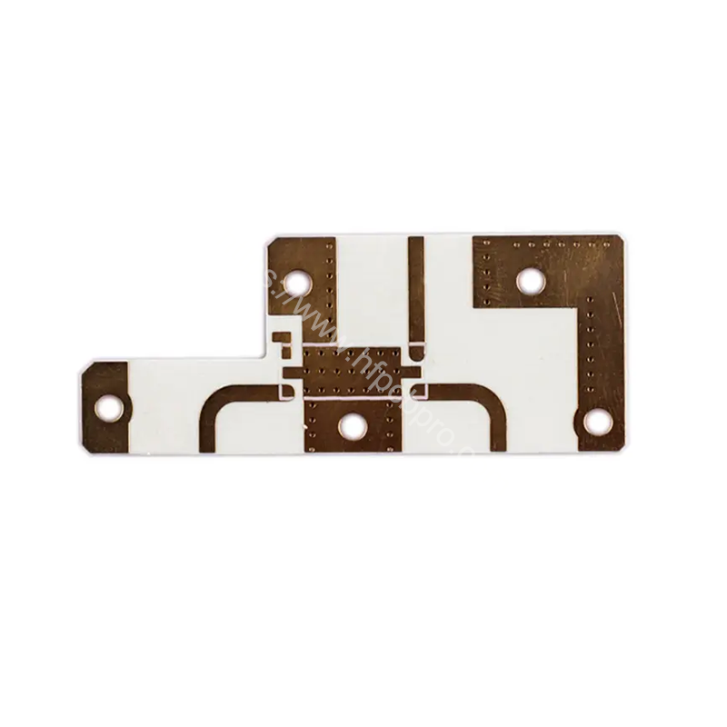
Rogers 5870 is a high-frequency circuit laminate engineered for demanding RF/microwave applications. It features a ceramic-filled polytetrafluoroethylene (PTFE) composite substrate, offering an ultra-low dielectric constant (D<sub>k</sub>) of 2.33 ± 0.02 and exceptionally low dissipation loss (D<sub>f</sub>) of 0.0012 at 10 GHz. Key attributes include outstanding dielectric constant stability over frequency and temperature, a coefficient of thermal expansion (CTE) closely matched to copper for enhanced plated through-hole (PTH) reliability, low moisture absorption, and excellent processability similar to standard PTFE materials. Its combination of low loss and stable electrical properties makes it ideal for high-performance antennas, automotive radars (e.g., 77 GHz), aerospace systems, and advanced communications infrastructure.
| Number of layers | 2L |
|---|---|
| Material | Rogers RT5870 |
| Board Thickness | 1.575mm(62mil) |
| Copper Thickness | 1/1oz(35um) |
| Quanlity Standard | GJB362B |
| Dielectric Constant (Dk) | 2.33 @10GHz |
| Dissipation Factor (Df) | 0.0012 @10GHz |
| Applications | Microwave PCBs for Signal Processing |
| Surface Finish | ENIPIG 1u |
Rogers Corporation's RO5870™ high-frequency laminate series is a premier choice for advanced microwave and millimeter-wave circuit designs requiring ultra-low signal loss and exceptional electrical stability. This material utilizes a unique ceramic-reinforced polytetrafluoroethylene (PTFE) composite as its dielectric core.
Engineered for superior high-frequency performance, RO5870 exhibits an ultra-low dielectric constant (D<sub>k</sub>) of 2.33, tightly controlled to within ±0.02. This exceptionally consistent D<sub>k</sub> minimizes phase variations critical for precise signal timing in complex circuits. More significantly, it delivers an extremely low dissipation factor (D<sub>f</sub>) of just 0.0012 @ 10 GHz, making it among the lowest loss commercially available laminates. This ultra-low loss characteristic is maintained over a broad frequency spectrum and across a wide operating temperature range (-50°C to +150°C), ensuring minimal insertion loss degradation in high-power or thermally challenging environments.
Beyond its outstanding electrical properties, RO5870 offers excellent mechanical stability. Its z-axis coefficient of thermal expansion (CTE) is closely matched to that of copper foil. This CTE matching significantly enhances the long-term reliability of plated through-holes (PTHs) and multilayer structures by reducing thermo-mechanical stress during thermal cycling. The laminate also boasts very low moisture absorption (<0.02%), further contributing to stable performance in humid conditions. Despite its advanced properties, RO5870 maintains good processability, allowing fabrication using techniques common to standard PTFE-based microwave laminates.
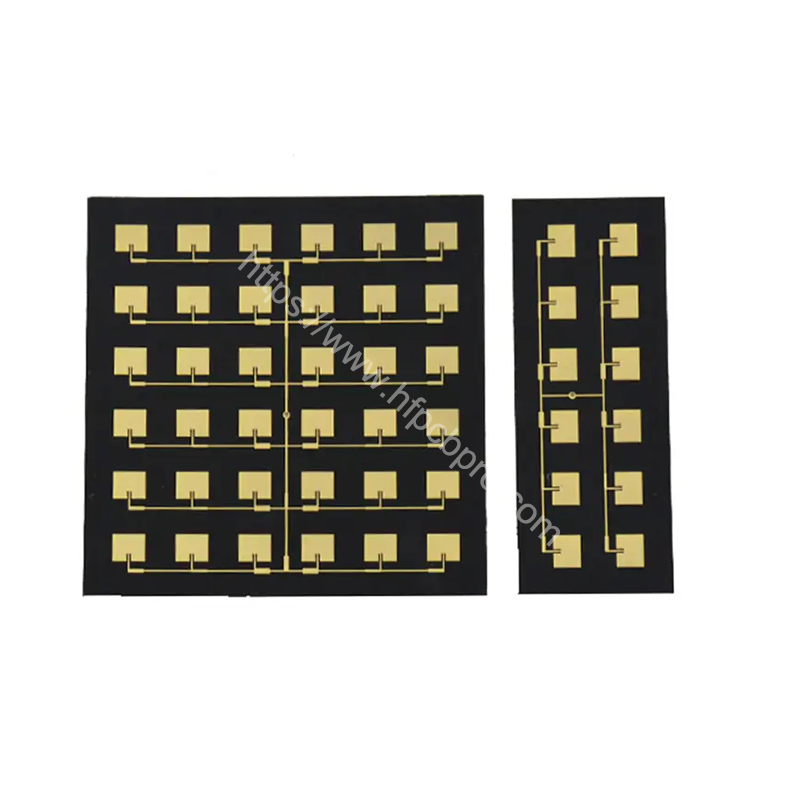
These attributes – ultra-low loss, stable dielectric constant, thermal reliability, and manufacturability – establish Rogers 5870 as a critical enabler for cutting-edge applications. It is extensively used in high-performance microstrip and stripline circuits, low-loss antennas, automotive radar sensors (including 77 GHz systems), aerospace and defense electronics, satellite communications, and next-generation wireless infrastructure demanding the highest efficiency and signal integrity at microwave and millimeter-wave frequencies.
We offer a variety of high-frequency materials, including Rogers (e.g., RO4350B, RO5880), Taconic, and PTFE, depending on customer requirements.
Absolutely, we can provide detailed datasheets for review.
Our high-frequency PCBs can support frequencies up to 110 GHz, depending on the design and materials used.
We ensure precise impedance control through accurate stackup design, detailed impedance simulations, and advanced manufacturing processes.
Yes, we can combine materials like FR4 and high-frequency laminates for hybrid PCBs.
Restrictions mainly involve minimum trace width/spacing and material selection, depending on your design requirements.
We enhance thermal performance by using high thermal conductivity materials (e.g., metal-based PCBs) and optimizing copper thickness.
Thermal conductivity ranges from 0.2 W/m·K to 1.0 W/m·K, depending on the material.
ENIG/Gold Plating/Immersion Silver/Silver Plating/HASL/Gold finger/OSP/Nickel-palladium Gold/Resin plugging/Countersinking/ENIG+Hard Gold Plating/ImNi+ImTin/ENIG+OSP
ENIG is recommended due to its flat surface and excellent conductivity for high-frequency use.
We can produce high-frequency PCBs with layers ranging from 2 to 72.
Yes, we specialize in multilayer high-frequency PCBs and support hybrid stackup processes.
The thickness tolerance is ±0.05 mm, and the trace width tolerance is ±10%.
We perform impedance testing, RF performance testing, vacuum thermal testing, and more.
We achieve this by using high-quality materials, optimized manufacturing processes, and strict control of board thickness and other parameters.
Answer: Prototypes typically take 2–7 business days, while mass production takes 6–15 business days, depending on order volume and complexity.
High-frequency materials (e.g., Rogers) are more expensive, and higher layer counts increase complexity and cost.
We ensure reliability by using high-quality materials, rigorous testing, and optimized manufacturing processes.
Yes, our PCBs can endure temperatures up to 260°C and are suitable for harsh environments.
We use anti-static bags, vacuum packaging, and shockproof padding in the outer cartons for protection.
We provide air freight, express delivery, and sea shipping, depending on your needs, DHL is always prefered that ensure timely delivery through reliable logistics.