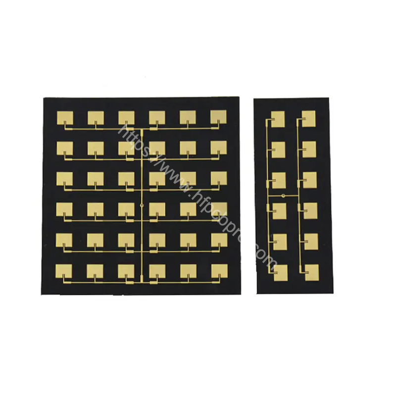
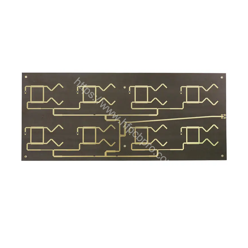
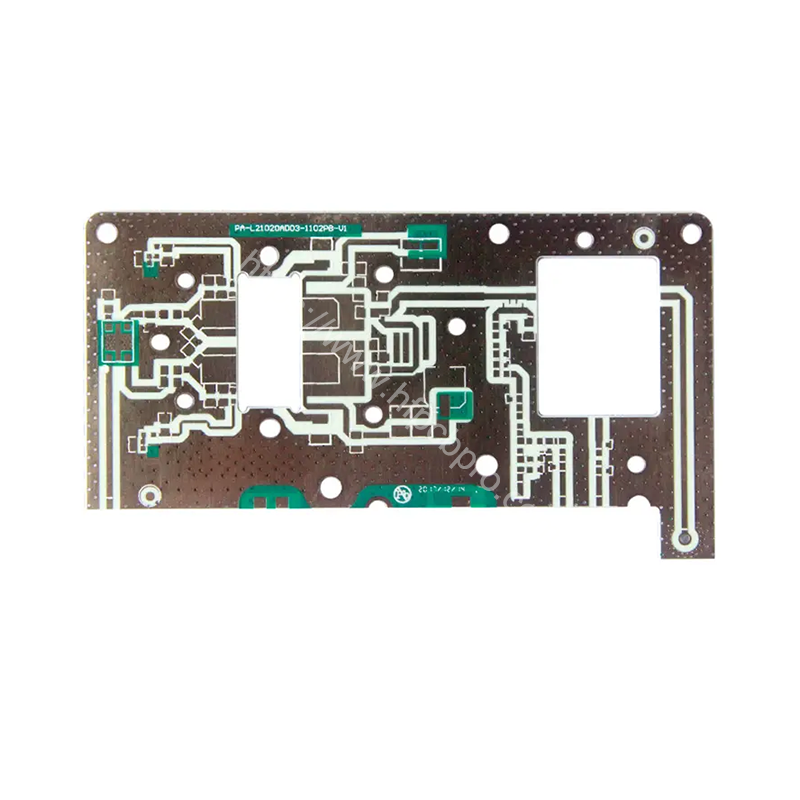
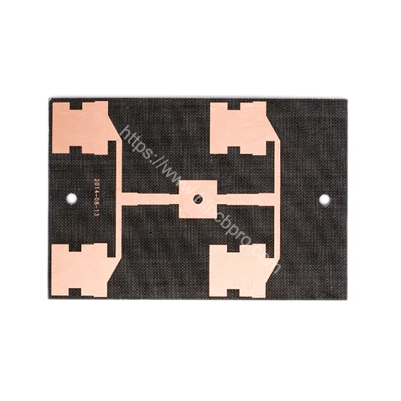
4-layer RO4350B PTFE-based laminates High frequency PCB is a high-performance solution designed for High Frequency PCB applications. Key features include Number of layers: 4, Dissipation Factor (Df): 0.0037.
| Material | Rogers RO4350B |
|---|---|
| Board Thickness | 1.6 mm (63 mil) |
| Copper Thickness | 1/1/1/1oz(35um) |
| Quanlity Standard | IPC-Ⅱ |
| Dielectric Constant (Dk) | 3.48 @10GHz |
| Dissipation Factor (Df) | 0.0037 @10GHz |
| Applications | antenna radar |
| Surface Finish | ENIG 2u |
Board Material Introduction:
The RO4000® series high-frequency circuit board materials deliver superior RF performance at low production costs. With low-loss characteristics and processing techniques similar to conventional epoxy/fiberglass (FR4), they offer strong price competitiveness.

When circuit operating frequencies exceed 500MHz, designers face limited material options. The RO4000 series enables RF engineers to efficiently design circuits—such as impedance matching networks and controlled-impedance transmission lines—while its low dielectric loss provides unmatched advantages in high-frequency applications. Its dielectric constant (Dk) exhibits minimal temperature variation (among the lowest in its class) and remains highly stable across broad frequency ranges.

The coefficient of thermal expansion (CTE) of RO4000 materials also benefits circuit designers. CTE compatibility with copper ensures exceptional dimensional stability, critical for multilayer designs. Even under severe thermal cycling, the low Z-axis CTE of RO4000 materials guarantees plated through-hole (PTH) reliability. A glass transition temperature (Tg) > 280°C (536°F) ensures stability throughout board processing.

Notes:
RO4350B 4mil thickness: Dk = 3.33 ± 0.05, compliant with IPC-4103A/240 spec. Other thicknesses follow IPC-4103A/11 and /240 specs.
Recommended Dk values: Based on average measurements from multiple material batches, correlated with solder mask thickness (s) for modeling.
LoPro® Laminate Warning:
RO4350B LoPro cannot share UL certification with standard RO4350B. Separate UL qualification may be required.
LoPro uses modified RO4000 resin for reverse-treated foil bonding.
LoPro foil adds ≈0.0007” (0.018 mm) per layer.
LoPro resin Dk ≈ 2.4, but composite Dk (with base laminate) should reference datasheet averages.
Design Dk decreases ≈0.1 as core thickness drops from 0.020” to 0.004”.

Key Features:
RO4000 materials are glass-reinforced hydrocarbon/ceramic laminates (non-PTFE).
Performance-driven for high-volume: Tight Dk tolerance, low loss, superior electrical properties for high-frequency/broadband applications.
Stable electrical behavior across frequencies: Ensures repeatable impedance control (transmission lines, filters).
Low Dk variation vs. temperature: Excellent dimensional stability.
Low Z-axis CTE: Reliable plated through-holes (PTHs).
Low in-plane CTE: Stability across processing temperatures.
High-volume manufacturing ease: FR4-compatible processes ensure cost efficiency.
Conductive anodic filament (CAF) resistance.

Typical Applications:
Satellite TV LNBs (Low-Noise Block Downconverters)
Microstrip circuits, cellular base station antennas & power amplifiers
Automotive radar/sensors
RFID tags
We offer a variety of high-frequency materials, including Rogers (e.g., RO4350B, RO5880), Taconic, and PTFE, depending on customer requirements.
Absolutely, we can provide detailed datasheets for review.
Our high-frequency PCBs can support frequencies up to 110 GHz, depending on the design and materials used.
We ensure precise impedance control through accurate stackup design, detailed impedance simulations, and advanced manufacturing processes.
Yes, we can combine materials like FR4 and high-frequency laminates for hybrid PCBs.
Restrictions mainly involve minimum trace width/spacing and material selection, depending on your design requirements.
We enhance thermal performance by using high thermal conductivity materials (e.g., metal-based PCBs) and optimizing copper thickness.
Thermal conductivity ranges from 0.2 W/m·K to 1.0 W/m·K, depending on the material.
ENIG/Gold Plating/Immersion Silver/Silver Plating/HASL/Gold finger/OSP/Nickel-palladium Gold/Resin plugging/Countersinking/ENIG+Hard Gold Plating/ImNi+ImTin/ENIG+OSP
ENIG is recommended due to its flat surface and excellent conductivity for high-frequency use.
We can produce high-frequency PCBs with layers ranging from 2 to 72.
Yes, we specialize in multilayer high-frequency PCBs and support hybrid stackup processes.
The thickness tolerance is ±0.05 mm, and the trace width tolerance is ±10%.
We perform impedance testing, RF performance testing, vacuum thermal testing, and more.
We achieve this by using high-quality materials, optimized manufacturing processes, and strict control of board thickness and other parameters.
Answer: Prototypes typically take 2–7 business days, while mass production takes 6–15 business days, depending on order volume and complexity.
High-frequency materials (e.g., Rogers) are more expensive, and higher layer counts increase complexity and cost.
We ensure reliability by using high-quality materials, rigorous testing, and optimized manufacturing processes.
Yes, our PCBs can endure temperatures up to 260°C and are suitable for harsh environments.
We use anti-static bags, vacuum packaging, and shockproof padding in the outer cartons for protection.
We provide air freight, express delivery, and sea shipping, depending on your needs, DHL is always prefered that ensure timely delivery through reliable logistics.